Assignment 6: Conditionally Computed Images
Due: 10:30 p.m., 3 March 2015
Summary:
You will create interesting images using
image-compute and related procedures.
Purposes: To gain further experience conditionals and have some fun with representations of images as functions.
Collaboration: You chose to work alone or were assigned partners in class.
Wrapper (Prologue): Individually read through this assignment and make sure that you understand what is required. Then use the form available at http://bit.ly/151hw6pro to indicate (a) how long you think this assignment will take and (b) what you think will be the most challenging aspect of this assignment.
Wrapper (Epilogue): When you are done with the assignment, fill out the form available at http://bit.ly/151hw6epi to indicate (a) how long the assignment took, (b) what the most challenging part of the assignment was, and (c) something important you learned from doing the assignment. If you find that the assignment took much less or much more time than you expected, also include (d) a note as to what might have led to that difference.
Submitting:
Email your answer to <grader-151@cs.grinnell.edu>. The title of
your email should have the
form CSC 151.00 Assignment 6: Polar Coordinates
and should contain your answers to all parts of the assignment.
Scheme code should be in the body of the message.
Warning: So that this assignment is a learning experience for everyone, we may spend class time publicly critiquing your work.
Preliminaries
In your initial explorations of the image-compute
model, you have been using the row and column of a pixel to generate
a color and create images. Creating shapes using rows and columns
often involves either using linear boundaries, or some complicated
calculations for doing things like circles. You may recall that using a
row and column to indicate location is called a “Cartesian”
coordinate system. However, there is an alternative that instead
specifies a radius and angle. The radius is the distance from some
origin point, and the angle is measured from some arbitrary direction
(such as eastward/rightward).
Thinking geometrically for a moment (rather than in our usual image coordinate system), the figure below shows the origin at (0,0), and the (x,y) Cartesian point (4,3). We could also express this point in polar coordinates as a (radius,angle) pair. In this case, the radius is 5 and the angle is about 36 degrees (or 0.6435 radians).
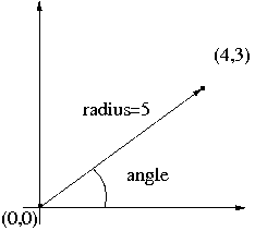
How do we get from cartesian coordinates to polar? Well, the radius is straighforward. This is the Euclidean distance from the origin; you may also see it as an application of the Pythagorean theorem: radius = sqrt(x2 + y2).
What about the angle? Well, if we think back to geometry, we know
that the tangent of an angle is the opposite side of a triangle
divided by the adjacent side. Thus, the tangent of the angle would
be y (the opposite side) divided by x (the adjacent side). Since we
want the angle itself, not the tangent, we must take the inverse
tangent, which is also called arctangent or atan, of the
quotient. Therefore, angle = atan(y/x). The DrRacket procedure
( gives that angle, even
when atan y
x)x is 0. However, there is no correct
answer when both x and y are zero; we return 0 in this case.
So can we write Scheme functions to implement these? Certainly:
;;; Procedure:
;;; cartesian->polar-radius
;;; Parameters:
;;; x, a number
;;; y, a number
;;; Purpose:
;;; Convert cartesian coordinates to a polar coordinate radius
;;; Produces:
;;; radius, a number
;;; Preconditions:
;;; [No additional]
;;; Postconditions:
;;; radius = sqrt( x^2 + y^2)
;;; radius >= 0
(define cartesian->polar-radius
(lambda (x y)
(sqrt (+ (square x) (square y)))))
;;; Procedure:
;;; cartesian->polar-angle
;;; Parameters:
;;; x, a number
;;; y, a number
;;; Purpose:
;;; Convert cartesian coordinates to a polar coordinate angle
;;; Produces:
;;; angle, a number
;;; Preconditions:
;;; [No additional]
;;; Postconditions:
;;; -pi <= angle <= pi
;;; If x is 0 and y is positive, y/x is undefined. However, trigonometry
;;; suggests that this "degenerate triangle" has an angle of pi/2, and
;;; so this procedure returns pi/2.
;;; If x is 0 and y is negative, y/x is undefined. However, this
;;; procedure returns -pi/2.
;;; If x and y are both 0, the angle is undefined. However,
;;; this procedure returns 0.
(define cartesian->polar-angle
(lambda (x y)
(if (and (zero? x) (zero? y))
0
(atan y x))))
Once we have polar coordinates in hand, it becomes very easy to express shapes. For instance, a circle is all the pixels where radius is less than or equal to some constant.
First, we make the center of a square image the (x,y) origin of the Cartesian coordinate system by translating any row or column by half the image size. Given this x and y, we can use our conversion procedures above to calculate the radius and angle for that location. Finally, coloring in the circle is simply a matter of checking the condition whether the radius of a point in polar coordinates is inside or outside the circle. If the circle has a diameter of 20, then we'd check whether the radius (of a pixel's location in the polar coordinates) is less than or equal 10.
Thus, we might write an expression like the following.

|
(image-compute
  (lambda (col row)
    (let* ([x (- col 25)]
           [y (- row 25)]
           [radius (cartesian->polar-radius x y)]
           [angle (cartesian->polar-angle x y)])
      (if (<= radius 10)
          (irgb 255 0 0)
          (irgb 0 0 0))))
  50 50)
|
As you might imagine (or hope, for all this reading you're doing), there is an entirely different category of shapes you can create using polar coordinates. For instance, what happens if, rather than keeping a constant radius, as in a circle, we varied the radius with the angle around the origin? One example of this is something called the "polar rose," so named because it can resemble a flower. The equation for the polar rose is radius = 1 + sin(n * angle). A deceptively simple equation gives some remarkable visual properties. Using the circle code above as a template, we can package this into a procedure that gives us some useful behavior.
;;; Procedure:
;;;   polar-rose
;;; Parameters:
;;;   petals, an integer
;;;   size, an integer
;;; Purpose:
;;;   Compute an image of a flower using polar coordinates
;;; Produces:
;;;   image, an image
;;; Preconditions:
;;;   [No additional]
;;; Postconditions:
;;;   (image-height image) = (image-width image) = size
;;;   image contains a visualization of the polar rose
(define polar-rose
  (lambda (petals size)
    (let ([x-center (/ size 2)]
          [y-center (/ size 2)])
      (image-compute
       (lambda (col row)
         (let* ([x (- col x-center)]
                [y (- row y-center)]
                [radius (cartesian->polar-radius x y)]
                [scaled-radius (* 4 (/ radius size))]
                [angle (cartesian->polar-angle x y)])
           (if (<= scaled-radius (+ 1 (sin (* petals angle))))
               (rgb-new 255 0 0)
               (rgb-new 0 0 0))))
       size size))))
Notice that we have given the multiplier inside the sine function an
interpretation. Namely, we have called it
petals. We have also generalized the code
above so that size of the image produced is a parameter. In order
to keep the figure entirely within the image, we have scaled the
radius down. Instead of just drawing the points where the radius
equals the computed value, we accept all smaller radii (so that the
rose is filled in). These last two changes are not strictly
necessary, but makes for a prettier, more complete picture.
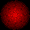
What happens when you use the procedure? You might try it out
with several different values for petals,
both small numbers and large numbers.
For example:
(image-show (polar-rose 4 100))
|
 |
(image-show (polar-rose 8 100))
|
 |
(image-show (polar-rose 64 100))
|
 |
Assignment
Problem 1: Bent Banana
The procedure polar-rose makes use of the polar
function radius = 1 + sin(petals * angle). This function is neatly
expressed in Scheme as follows
(lambda (angle) (+ 1 (sin (* petals angle))))
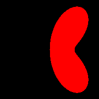
But there are a variety of other interesting shapes we can get by playing with different functions. Our colleague, Rhys Price Jones, has a function to make a blob that he calls the “bent banana”: cos(angle) + 4*cos(angle)*sin2(angle).
Make a function, (
using the following steps.
bent-banana
color size)
-
Copy the code for
polar-rose. -
Rename the function to
bent-banana. - In your copy replace the code for “1 + sin(petals * angle)” by code to calculate “cos(angle) + 4*cos(angle)*sin2(angle)”.
-
Notice that you no longer have any use for the parameter
petals, so remove it from your parameter list. -
We should generalize the color; modify your code for
bent-bananato take a color as input and render the blob in the specified color.
(bent-banana (irgb 255 0 0) 200) |
|
No, we don't know why he chose red for the banana. It's probably exotic (or what happens when you try to grow bananas in Wales).
Problem 2: Polar Shape
In problem 1 you modified polar-rose by hard
coding a different polar function of the form radius = __________.
Rather than changing small details by copying and modifying code in
Scheme, we prefer to parameterize such differences.
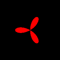
a. Write a procedure ( that produces an image using
your own polar equation by generalizing
polar-shape
polar-fun color
size)bent-banana and
polar-rose.
(polar-shape (lambda (angle)
               (* (cos angle)
               (- (* 4 (square (sin angle))) 1)))
             (irgb 255 0 0)
             200)
|
|
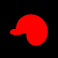
(polar-shape (lambda (angle) (/ (+ (sin (expt 2 angle)) 1.7) 2))
             (irgb 255 0 0)
             200)
|
|
Problem 3: Blended Shapes
The functions polar-rose and
polar-shape depict the shapes using solid blocks
of black and red. Create your own variation called
polar-rose-blend. In this variation, change the
arguments to irgb so that it produces an
interesting color blend based on the polar
coordinates (radius and angle). You may add any other parameters to the
polar-rose-blend you find useful.
Here are just two examples of many possibilities.
 |
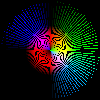 |
Explain why you chose the blend you chose, and how the blend is supposed to work.
Problem 4: Creative Images
a. Using polar-shape, polar-rose-blend or some related derivative,
write a program that creates and shows two interesting images.
b. Write a paragraph explaining what the parts of your images are. Include this paragraph in your code, commented out with semicolons.
Note that you can find many polar equations that produce interesting
graphs on the web. The site http://www-groups.dcs.st-and.ac.uk/~history/Java/index.html
has several applets displaying interesting curves, some
of which have accompanying polar equations. You will need to
“translate” any polar equations into Scheme as we did in the
Preliminaries and Problem 1. For example, the equation radius = 1 +
sin(angle) could be effectively expressed as (lambda (angle) (+ 1
(sin angle))). You can consider some wild and wonderful functions
that can incorporate other trigonometric functions (e.g., cosine or
tangent), or using conditionals to further vary the behavior (i.e.,
radius is one thing under one condition or something else under
another). You could also use a combination of these ideas. Of
course, the sky is the limit and you should not feel constrained to
just these possibilities.
Acknowledgments
This assignment, particularly the organization of the procedures in the preliminaries, was inspired by the final project work of Fall 2008 CSC-151 student Iliana Radneva '09.
Our colleague Rhys Price Jones contributed the bent banana of Problem 1 and the generalization of Problem 2 (along with the images for those problems).
Important Evaluation Criteria
We will evaluate your work on the correctness, clarity, and concision of your code. We will also look for evidence of creativity and innovation in your solutions to Problems 3 and 4.